CQ-DATV issue 9 published by Ian G8IQU in March 2014 , contained an article written by Trevor, G8CJS on the first ATV repeater in Yorkshire. It is reproduced here, edited for the website. The original article can be found here: https://cq-datv.ianp.uk where you’ll find an archive of all 100 issues.
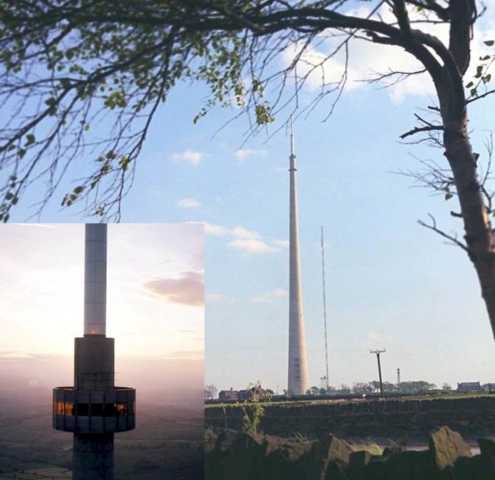
This is the story behind the design, construction and installation of the now defunct 24cms ATV repeater GB3ET. For those of you that do not know, ET stands for Emley Television. Emley Moor is the main television transmitter for Yorkshire and uses a 900ft transmitting tower that can be seen from the northern section of the M1 motorway. Being a tower, rather than a mast, it has an equipment room at the top called the Turret Room that has lift access and was to be the designated home of the hardware for this proposed repeater.
The original concept for a 24cms ATV repeater was the brain child of David Long, G3PTU, who was at the time (early 80’s), an Engineer working for the then IBA (Independent Broadcasting Authority) and employed at the Emley Moor site. David drafted and submitted the application for the repeater and the NoV (the license) came through rather unexpectedly. No hardware existed at all, so David rang and
asked if BATC could help. We had the old BATC member’s services shop back then, but not much in the shop could be used to build a repeater; all that was about to change. 24cms ATV transmitters and satellite receivers were around, but not PCB’s that could be populated up to control an ATV repeater.
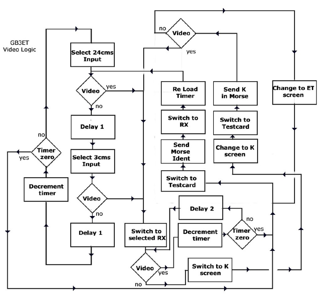
My first thought was the logic. Time to design a repeater logic, and ET was going to be the test bed. After a couple of attempts, I came up with the following flow chart, which not only fitted the bill, but also had provision for a second 3cms TV input. It was designed so that if permission could be obtained for a second receiver, it could just be added without any logic changes. Remember, this was not just about ET, it was about finding a universal solution to ATV repeater logic.
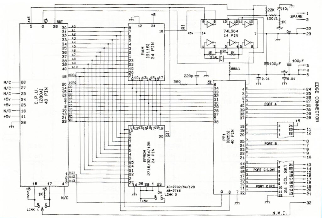
It became obvious that to make this flow chart work using TTL logic, it was going to require a considerable amount of logic functions, but if we used a microprocessor it could be reduced to 5 chips. The microprocessor was the obvious route, but the technology was going to be a challenge particularly the programming as I had never done any before. I went for modular construction using Euro cards and a rack frame. The first card, the Z80 micro controller, was made using wire wrap and went together in a couple of lunch times. Wire wrap is ideal for developing circuits with lots of wires and chips, but not many capacitors resistors or transistors because these need mounting on headers so that they can be plugged into a DIL socket and wired. The CPU had few of these and was ideal. Simple hand wire wrap tools require the special wire to be cut to length and stripped; the power version of this hand tool speeds things up by also doing the stripping. It’s important to put number tags on the DIL sockets and to tick each connection on the circuit diagram so as to keep track. Once the wire wrap was complete and checked out with a simple continuity checker, the chips were fitted and the CPU was powered up.
Alas it did not work, or did it? Having never designed a circuit which uses a micro, or programmed one before, this was all a first. In fact I had never written an EPROM for a micro so it was difficult to work out if it was my programming, my hardware design, my wire wrap prototype or all three that were at fault. The problem was the 8255 PIO (the chip that would provide the input output) would not initialise and stubbornly remained in tri state. I wrote several other small routines that terminated in Halt, which pulls down the halt pin and stops the program and they worked, so perhaps the micro board was part working. Checking and rechecking the data books on Z80 and the 8255 did not produce the answer; the 8255 is a brilliant chip, but was designed to work with the 8080 CPU not the Z80.
I was starting to worry about that part of the design when I finally solved the puzzle. The hardware reset resets both the 8255 and the Z80 at the same time, but there was no data written in either book about recovering from a reset and the unpublished fact is the Z80 recovers first and starts running instructions that the 8255 is not ready to receive and as every program I had written started talking to the 8255 immediately after reset, it was ignoring the instructions until it had recovered from its own reset long after the Z80 had pushed the instructions to it. A quick revision of the software to include a delay routine before 8255 initialisation and the problem was solved.
I should explain the programming was done by looking up the Z80 instructions in a book, converting the instructions to HEX and then typing them into a keyboard EPROM programmer. Working this way is a little like creating a book on a typewriter, but with no way of making corrections. Any changes or corrections required the book to be re-typed from scratch. This works for small programmes, but the larger the program the more the changes hurt. What I needed was an assembler coupled to an EPROM programmer. This would upgrade the typewriter to a word processor, so changes could be made without a retype. I did get to implement this technology onto a Spectrum Computer, but not until after GB3ET was built, programmed and running. It proved a very useful tool for refining later software revisions. The Spectrum EPROM Programmer was just one of the projects in the Micro and Television Handbook, (archived here https://batc.org.uk/atv-handbooks).
One week into the ET build we had logic running, not bad. Well it would have been quicker if it had not been for a procession of people banging on the workshop door because their VT machine was broken. Just because I was the on-duty VTR fixer was no excuse; it was quite obvious I was busy! The software needed lots of work to set up the time out loops and generate readable morse. Being a G8 (then a B class license) Morse code was beyond me, but there were several G3’s (A class license), on the telephone who would listen and comment. Eventually we had working software and pleasant Morse code identification (so I am informed).
The next stage was board 2 where we could interface video detectors and switching to the micro. Initially the video switching was relays that chattered and would probably have had a short life but modular construction meant better, more advanced, modules could be constructed and the present modules relegated to the spares box for emergency fixing and diagnosis. The audio was mixed, not switched; the idea came from a visit to Germany where I stayed at the QTH of Heinz DC6MR. He used to work through a dual input ATV repeater with the logic of first person to access either input has their sound and pictures relayed. The second person in, (other input) is audio only so you get duplex sound. Not only is it brilliant, but so easy to implement. I added the local PTT microphone so that anyone working on the repeater on site had one way communications and it proved very useful.
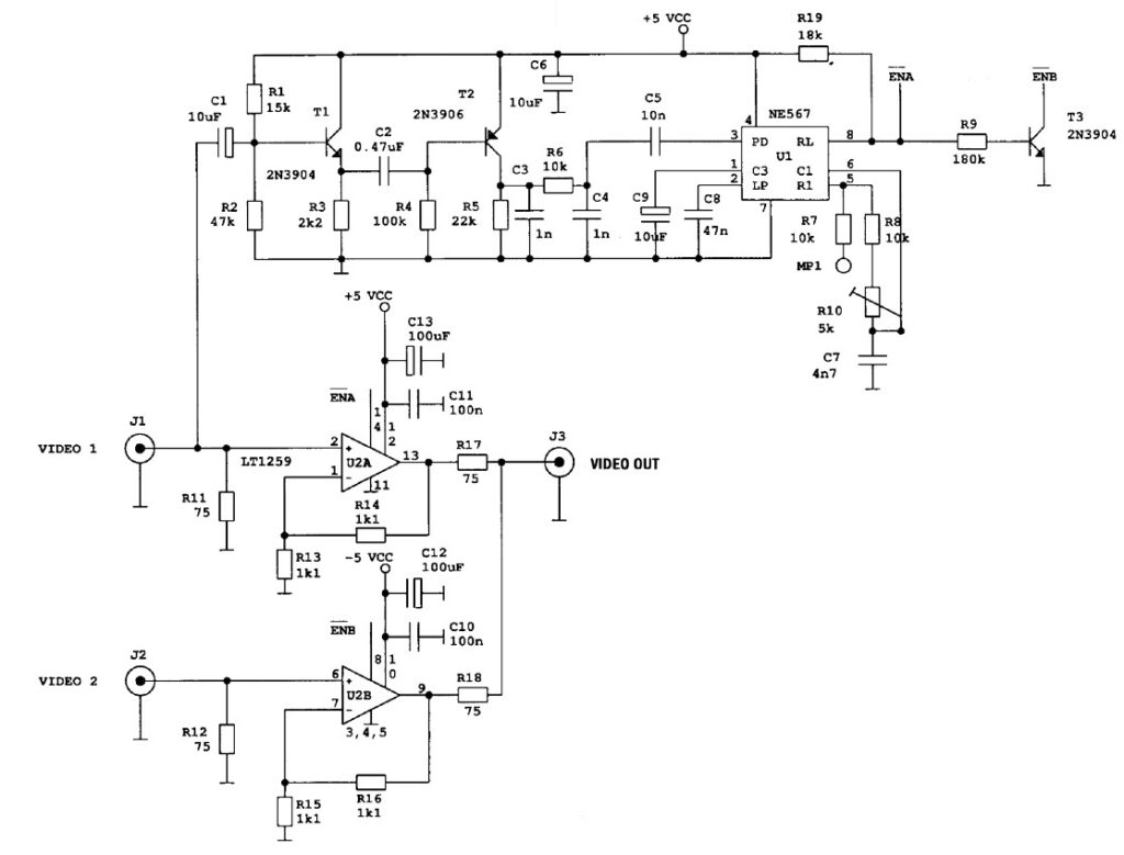
The video detector was the standard sync separator and tone decode PLL that nearly every repeater used at the time. The diagrams have long since gone, but this diagram that appeared much later in the Dutch ATV magazine Repeater (now also defunct) is as near as we can get to the detector used on ET. Hans Bruin (the author) also added electronic switching to his unit, which was also on the ET MK2 switching card. By the end of the second week and ET was making progress.
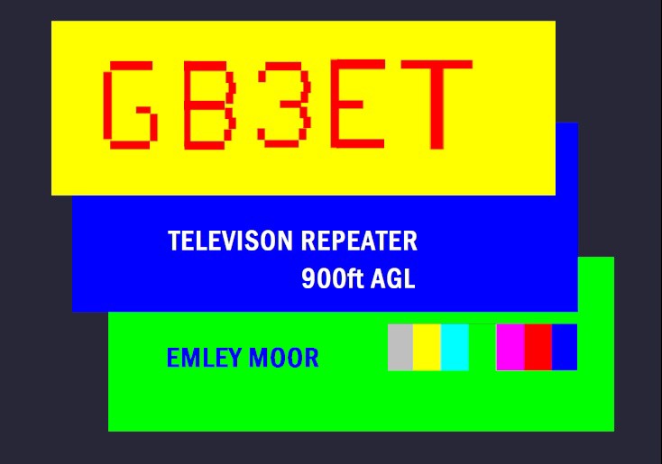
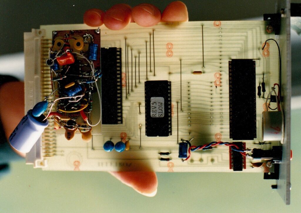
The next problem was the Electronic Test Card and like all good ideas the solution came from an unlikely source; this one was the company skip. A damaged TV receiver had been placed just outside the office door; the TV set was beyond repair, but it had a salvageable Teletext decoder. Teletext, an obsolete system, was a stream of data transmitted by the broadcasters in the vertical interval. The selected page could be stored in RAM memory and displayed on the screen. Replace the RAM memory with an EPROM and you can program not only a test card, but a display that will fill nearly all the TV screen with rather chunky graphic blocks or text. The salvaged decoder would not fit the card frame, but it yielded the idea and the chip set. It meant writing another EPROM and designing the unit and wire wrapping it up. I added page switching to the EPROM, so we had the ET screen and the time out K. I was at the time undecided about the Teletext pattern for time out, I had envisaged a test card, but it turned out to be a good decision to use the K.

The first version of the repeater logic was prone to crashes, but the problem could never be replicated in the workshop. The fix was twofold. First I replaced the CPU card with a PCB one and secondly I added a watch dog. This is a simple timer that periodically generates a CPU reset pulse. Normally, the pulse is never delivered because the CPU keeps resetting the timer via a PIN on the 8255, however if the computer crashes then no reset pulses are received and the timer completes its cycle causing the CPU to be reset.
In the MK2 Logic the EPROM pages were supplemented by a RAM page that could be updated over the air via remote keyboard access. The data was pure ASCII text and was sent as a dual data tone on the ET audio Channel. This made possible a news screen for the area, explaining any changes to ET, promoting local amateur events, and apologising for any ET outages of which there were some in the early days, due to CPU crashes.
This design was later reproduced in the ATV Compendium (archived here https://batc.org.uk/atv-handbooks) and proved very popular with other repeaters right down to the test card display. It was RGB out and required a PAL coder. Initially used the TEA 2000 which was popular in TV games consoles. At the end of week three and we had the time out screen and K screen.

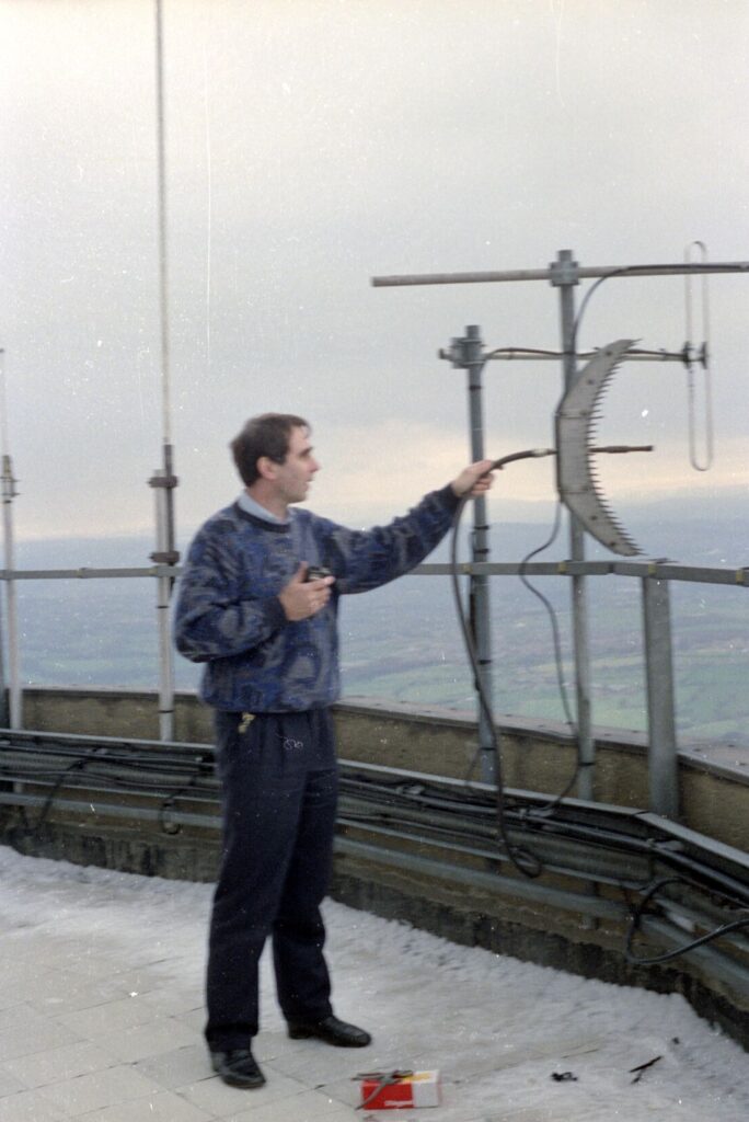
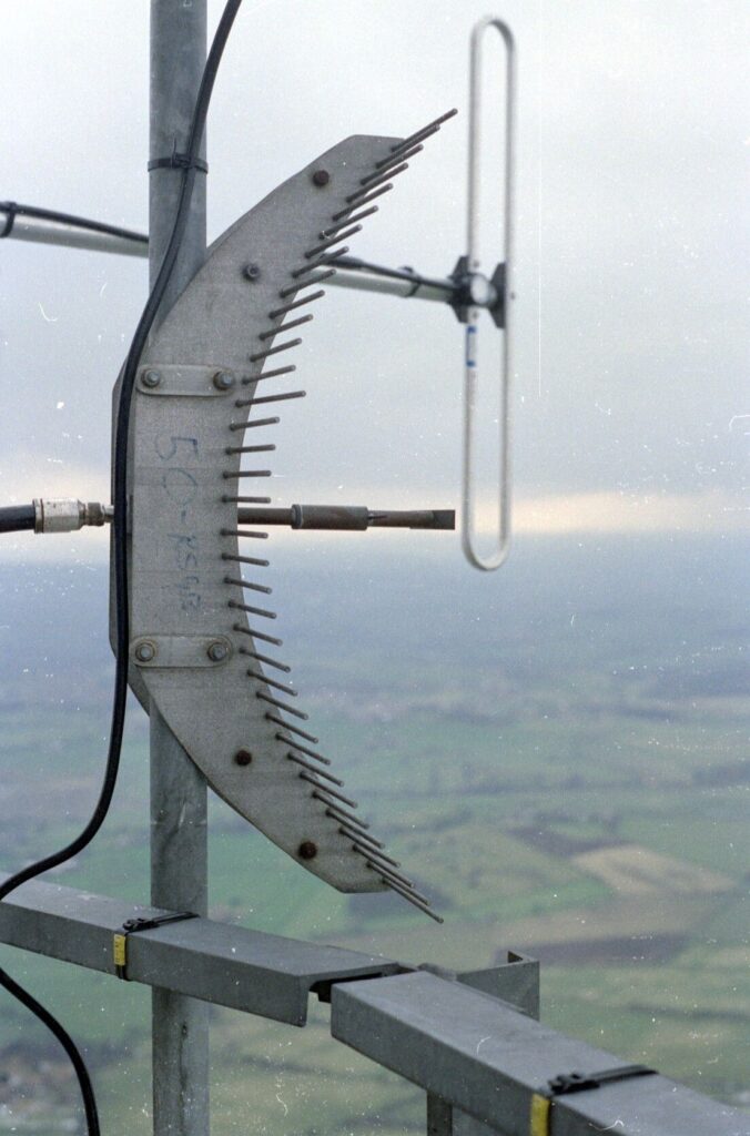
A colleague at Yorkshire Television, Peter G3PYB, turned up and really was a blessing. Peter was always an RF man, the expert on FM ATV and he worked in the same building. We became great friends and I know without his help GB3ET would have never radiated its signal around Yorkshire. Peter fitted the Alford slot some 80 ft above the Turret room, but left me to bolt the TX antenna in place on the Turret roof, 1200ft above ground and on a windy day; it was the most scary thing I have ever done in the name of ATV.
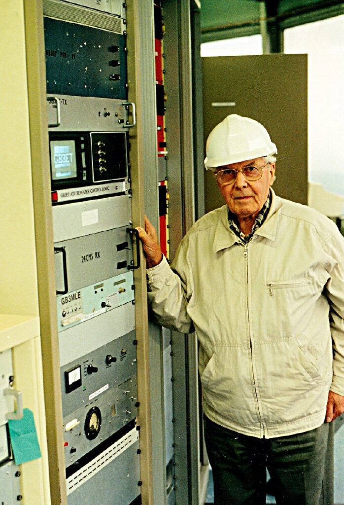
I had hoped for a grand switch on and I had in mind Grant Dixon, G8CGK, one of the founder members of BATC, but alas he was not available. Some years later he visited Yorkshire and ascended the tower to approve of our work and see the fully populated rack, that Peter and I had put in place some years earlier. Space in the GB3ET rack in the Turret room was provided for other amateur projects, such as a microwave beacon and a proposed packet repeater as seen below.
By the end of week 6, I rang Dave Long, G3PTU and announced that GB3ET was built, fitted and working. His idea was now a reality. It was only 200mw, but a PA, which then flagged up the requirement for RF filters, soon followed. Sadly, the IBA became NTL some years later, and the peppercorn rent on the rack shared by all the amateurs with projects in situ was revised to unaffordable figures. The relationship ended and GB3ET, along with the other amateur projects, were switched off. I have never been back to the Turret Room since I took the photo of the late Grant Dixon. The hardware was not wasted though, as it was relocated to Queensbury and given the new call sign GB3YT.
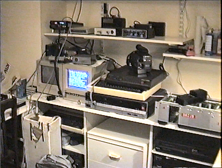
G8VAT’s Photos