2015 – 2022
Construction of the repeater began in April 2015 and operation of commenced in August 2015. By July 2018 it had got analogue and digital inputs on 23cm and a digital 70cm input. It acquired a 6cm analogue input by January 2021.
The repeater was located in Mirfield West Yorkshire, receiving on 1276MHz Digital or Analogue, 437Mhz Digital, 5665Mhz Analogue, and Transmitted on 1316MHz Digital output only. GB3YT had been on air since August 2015 until November 2022 when a fault developed.
YT also had a 144.750MHz talkback input which is re-transmitted on the right audio channel when a valid video signal was received – this 2m input also required a CTCSS of 118.8Hz enabled.
GB3YT was owned and run by G8NZR (Kay) and G8POK (Graham); they were not part of, or affiliated to, any groups, clubs or organisations and voluntarily gave up their time and resources to provide the repeater. If the repeater went off-air for any reason, time and access for repairs was limited, so patience was required.
In 2023, Kay and Graham felt that they could not continue to support the maintenance of the repeater because of the poor access to where the cabinets were located in the roof space of a barn. Low usage and ongoing costs were also a concern, so reluctantly they decided to withdraw the service.
How GB3YT was used
When using digital inputs, 5 seconds was needed at the beginning of an over for all the digital circuitry to lock onto the signal. Analogue circuitry locked onto the video signal and switched the logic fairly quickly. Access was successfully made if a repeated audio ident plus ‘K’ and they; GB3YT test card J was received from the repeater when carrier dropped. After approximately 30 seconds, the repeater switched back over to the outside camera or test card with ident and an audio GB3YT descriptive ident every 5 minutes. If a signal was received on more than one input, then GB3YT displayed a quad picture and showed up to four input signals. The system t receive simultaneous signals on both 23cm analogue and 23cm digital for obvious reasons.
GB3YT – technical description
RF Inputs:
Input 1 – 1276MHz Digital 4Ms/s FEC 1/2 (Horizontal polarisation on 23cm) DVB-S
Input 2 – 1276MHz Analogue Horizontal pol (FM 625 line – 6MHZ sound sub-carrier) PAL
Input 3 – 437MHz Digital 2Ms/s FEC1/2 (Vertical polarisation on 70cm) DVB-S
Input 4 – 5665Mhz Analogue Vertical pol (FM 625 line – 6.5MHz sound sub-carrier) PAL
RF Output:
Output – 1316MHz Digital 4Ms/s FEC 1/2
Digital Video PID – 256 (0100 hex)
Digital Audio PID – 257 (0101 hex) – See Audio channel TX useage below
Digital Tx Power – 25w ERP
Audio:
2m Talkback – 144.750MHz (CTCSS 118.8Hz) – Retransmitted on the digital right audio channel only.
Input digital audio – Retransmitted on the digital left audio channel only.
Input analogue audio – Retransmitted on the digital left audio channel only.
Standby audio/testcards transmitted in stereo.
Aerials:
23cm TX/RX – Alford slot at 35ft AGL horizontal pol
2m/70cm RX – Diamond collinear vertical pol
6cm – LCom HG5158UP-NF Omnidirectional vertical pol
Ground level – 550ft ASL
Location – IO93dp – Mirfield, West Yorkshire
General & Power
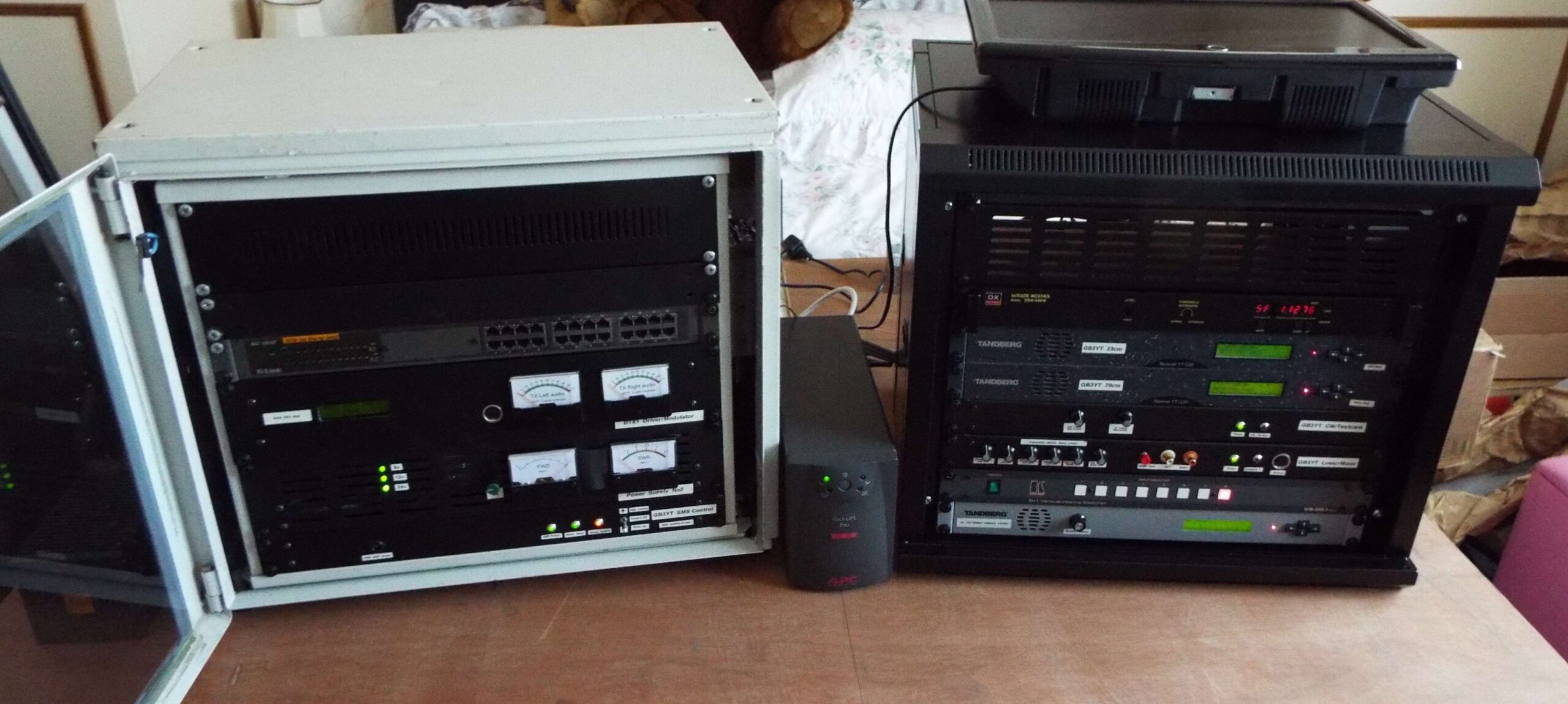
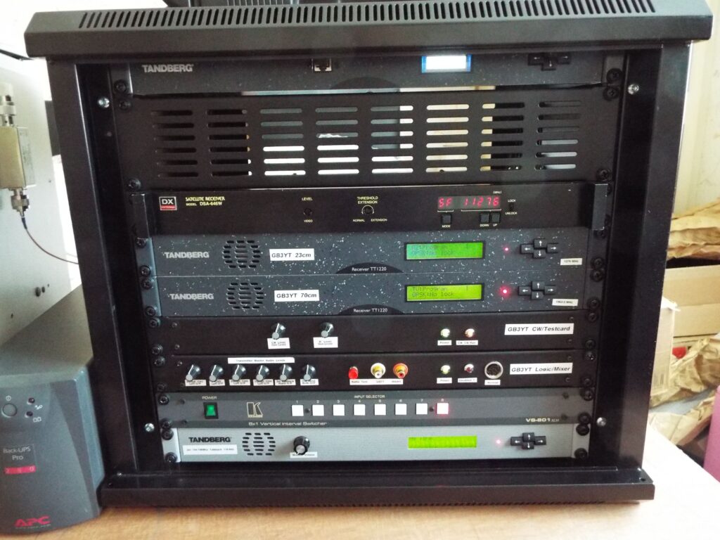
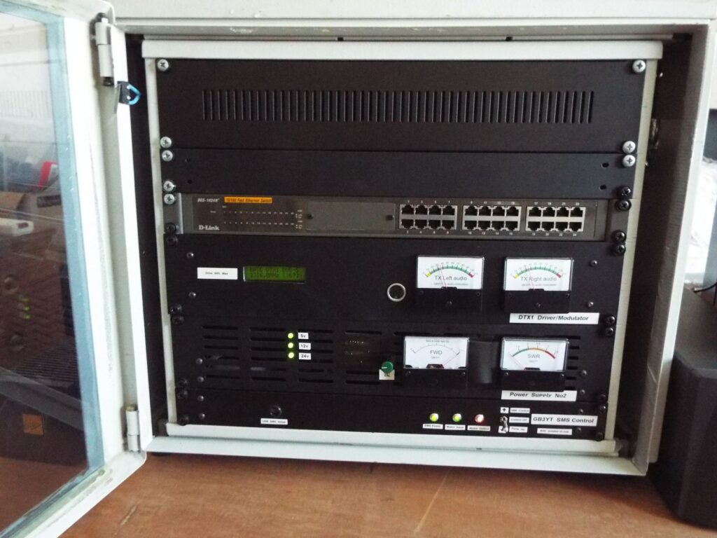
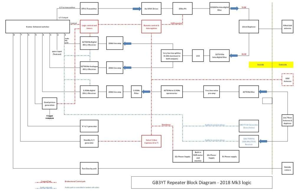
The GB3YT repeater was a combination of home brew and high quality commercial units built into two 19in compact 9u racks. The transmitter rack was powered by two large switch mode power supplies, one at 12v the other at 24v, and the receiver rack had a smaller 12v one also. A general layout block diagram is shown under the pictures tab above. Power failures and system problems were notified directly by email and text messages.

Antenna system
The antenna system consisted of an Alford slot mounted on a small mast which was fixed to the side of the building. This gave a total of around 35ft elevation above ground level. The mast also carried a high sensitivity colour camera which was used to generate a panoramic view from the hill top in Mirfield – this being broadcast when the repeater was not in use. This was replaced by a testcard from time to time when testing, or if the camera view was poor or not available. The feed from the antenna was directed into a set of small cavity duplexers which split the receive and transmit signals, which were then in turn fed through two separate five pole interdigital filters. This resulted in a very clean transmit signal, and provided a very clean receive signal into the low noise/high gain pre-amp.
The 23cm transmit signal was fed to the Alford slot which along with various feeder cable losses gave a calculated ERP of 25w – The cables losses equalled the antenna gain!
For 2m/70cm receive, a Diamond colinear vertical was used. Due the site owner requesting the use of the same mast, it was mounted vertically downwards which did not cause a problem, however, it was shielded by the building to the West therefore reducing sensitivity in that direction.
For 6cm receive, a Omnidirectional vertical L-Com HG5158UP halfway up the mast was used.
Receive

23cm: The antenna was first connected to a lightning arrester, then through a Bird Thruline SWR monitor, a Procom low loss small cavity duplexer, and then into a five pole interdigital filter. This in turn was fed into a 23cm VLNA which had 44db gain. The signal from the VLNA was fed into a low loss signal splitter giving an output to a Tandberg TT1220 for digital receive, and a DX Antenna DSA646W for analogue receive.
2m/70cm: The antenna was a 2/70 colinear which was fed into a duplexer/splitter. The 2m feed was used for the talkback on 144.750MHz, and the 70cm was fed into a series of bandpass/bandstop filters and a low noise pre-amp. The resulting 70cm signal was then fed into an upconverter module, filtered again at 1932Mhz, another stage of LNA, which gave an output fed to another Tandberg TT1220 at 1.932GHz. The only problem was that signals from the West were partially shielded by the building – although the coverage from the West was already limited by the Pennines.
6cm: The antenna was connected directly to a Watkins Johnson low noise pre-amp and then into an RC832 receive module, and audio/video was fed back from the mast. This was all housed in a small box directly on the base of the antenna. The input needed a minimum of 2 seconds video & carrier to switch to your signal. The delay was introduced to stop spurious switching caused by local 5GHz signals.
Talkback Receive
The talkback receiver was a crystal controlled PYE M290 receiver section from a F494 base station, which is tuned to 144.750MHz. The 2m audio was muted until a valid signal with a CTCSS of 118.8Hz was received. This talkback audio was re-transmitted on the right audio channel only, and ONLY when a valid ATV signal is being received. 118.8Hz CTCSS was chosen since the frequency is not normally used in the area, therefore reducing the chances of spurious audio being re-transmitted or interfering with the talkback input.
Audio Channel TX Usage
The receive audio, standby audio and takback audio was routed through to different transmit channels following a similar method adopted by other repeaters. The receive analogue and digital L/R audio was retransmitted on the left audio channel only, the CW ident during use is transmitted on both the LEFT & RIGHT audio channel, and the 2m talkback audio was retransmitted on the right audio channel only. The ‘K’ and standby ident audio were transmitted on both LEFT & RIGHT audio channels. If no/wrong sound was experienced , then it was advisable to check that a 6MHz sub-carrier was used if using analogue, and monitoring the left channel if listening for through audio. The right channel was only used for talkback (2m) and stereo testcards.
Transmit

The heart of the transmitter system was based on the BATC DTX1 modulator. That provided all the necessary digital conversions to change from an analogue video/audio input, into a fully encoded digital RF signal – albeit at a very low level (-5dbm). The output from the DTX1 was fed into a MMIC pre-amp contained in the driver amplifier which boosted the low signal level to around 4watts. The output of this fed a 150w final PA running at an output of around 40w. This signal was then filtered by the interdigital filter and then fed into the duplexer (a total of 2db loss through both). This gave a transmit output power of 25w into the antenna feeder
The PA modules were mounted on two very large heatsinks which were fan cooled, with fan speed controlled dependent on the heatsink temperature.
Logic/Switching

The signal path had various bits of logic to time and switch the audio/video path. It was all home made in both design and construction. The CW audio ident was home made based on a tone generator circuit and an EPROM to contain the callsign information. Switching between the video and audio feeds was performed by a Kramer A/V switcher which was controlled by the home made logic controller. The logic had a quad video picture for multiple display of input signals – switched in if more than one signal was being received. The logic would only display one full screen received signal, and then switch to quad display if more than one was being received – in other words, a 70cm,a 23cm signal and a 6cm signal could be viewed at the same time!
External Camera
The external camera was showing the view in a south easterly direction, and had the following specs;
- 1/3in. Colour Sony EXVIEW II CCD
- High resolution
- 700TV Line (Colour)
- Day and Night
- Minimum Illumination : 0.005 Lux (F:1.2) (No IR illumination fitted)
- Auto White Balance
- Automatic Gain Control
- Waterproof
The Emley moor TV transmitter mast could be seen on the right of the picture – navigation lights being easily visible at night time. The second mast was on its right, was a temporary lattice mast while major works were carried out on the main tower.